Pure Electronics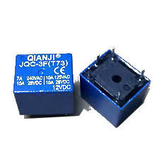
Relating to Relays
by Professor Petabyte
Introduction
An electronic relay is an electrically operated switch that allows a low-power signal to control a high-power
circuit. It consists of a coil, an iron core, a movable armature, and a set of contacts. When current flows
through the coil, it creates a magnetic field that pulls the armature, opening or closing the contacts to switch
the load circuit. When the coil is de-energized, a spring returns the armature to its original position. Relays
provide electrical isolation between control and power circuits, protecting sensitive components. They are used
in automation, motor control, automotive systems, and protection circuits. Modern types include solid-state
relays, which perform the same function electronically without moving parts, offering faster, quieter, and more
durable operation.
Why Relays are Important
Many systems rely on Microcontrollers for safe and effective operation. Microcontrollers
typically don't need much power and therefore require only a few volts to work - often
only 3-12volts DC.
This means they cannot drive power hungry devices like motors and heaters from their
output pins, but they can control relays which then work effectively as on/off switches
for more powerful sources of energy, e.g. 240vAC. Note also that relays are often driven
by Direct Current (DC) to control Alternating Current (AC) devices.
1. Overview of Electronic Relays
An electronic relay is an electrically operated switching device that uses a small control signal to open or close a
much larger electrical circuit. Relays act as intermediaries between low-power control systems (such as
microcontrollers, sensors, or digital circuits) and high-power loads (such as motors, lamps, or heaters).
Their fundamental purpose is isolation and amplification: a small, safe control voltage can operate a high-voltage
or high-current circuit without direct electrical connection. In this way, relays protect sensitive electronics and
provide reliable switching for loads that would otherwise damage control circuits.
Mouseover to Zoom
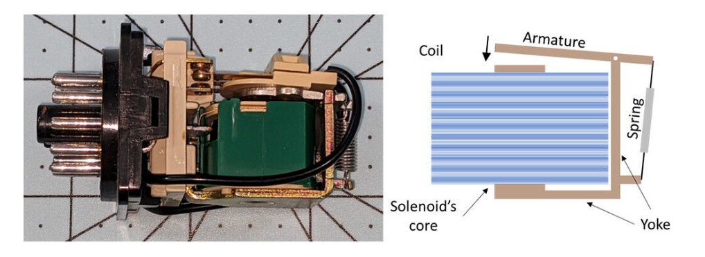
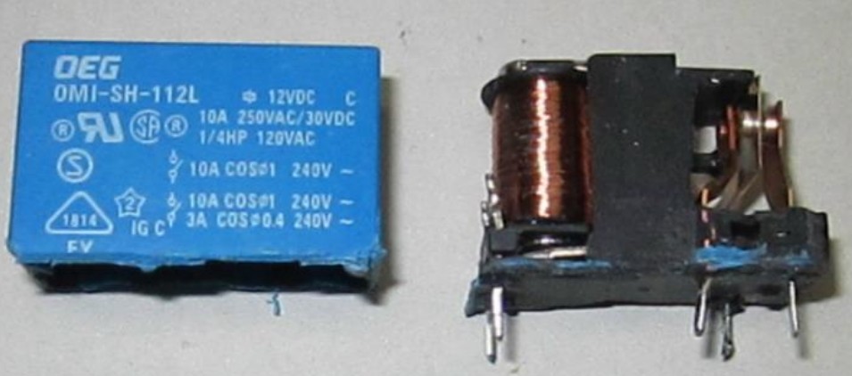
2. Basic Construction and Operating Principle
The classical electromagnetic relay consists of four main parts:
- Coil (Electromagnet):
A winding of fine copper wire around an iron core. When a current flows through the coil, it generates a
magnetic field.
- Armature:
A pivoted iron lever attracted by the electromagnet when the coil is energized. It physically moves to open or
close electrical contacts.
- Contacts:
Conductive elements (usually made from silver, copper, or alloys) that complete or interrupt the external
circuit. Contacts may be:
* Normally Open (NO): open until the relay is energized.
* Normally Closed (NC): closed until the relay is energized.
* Changeover (CO) or Double-Throw (DT): one common contact that switches between NO and NC.
- 4. Spring or Return Mechanism:
Returns the armature to its rest position when the coil is de-energized.
When the coil is powered, magnetic force overcomes the spring tension and moves the armature, changing the contact
positions. Removing power releases the magnetic field, allowing the spring to reset the contacts.
A flyback diode (in DC applications) or snubber circuit (in AC applications) is often added across the coil to
suppress voltage spikes caused by inductive collapse when the relay is switched off.
3. Major Types of Electronic Relays
Relays have evolved into many specialized forms, suited to different voltages, currents, and control methods. They
can be grouped into several broad categories:
Mouseover to Zoom
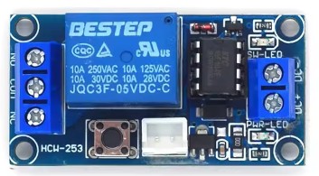
3.1 Electromagnetic Relays (EMR)
These are the traditional mechanical types described above. They use physical contacts that open or close when
actuated by an electromagnet.
Advantages:-
* Provide complete galvanic isolation between control and load.
* Can switch both AC and DC.
* Capable of handling high voltages and currents.
Disadvantages:-
* Mechanical wear and contact arcing reduce lifespan.
* Slower response (typically 5-20 ms).
* Audible clicking noise.
Applications:
Motor control, automotive circuits, HVAC systems, industrial automation, and power distribution.
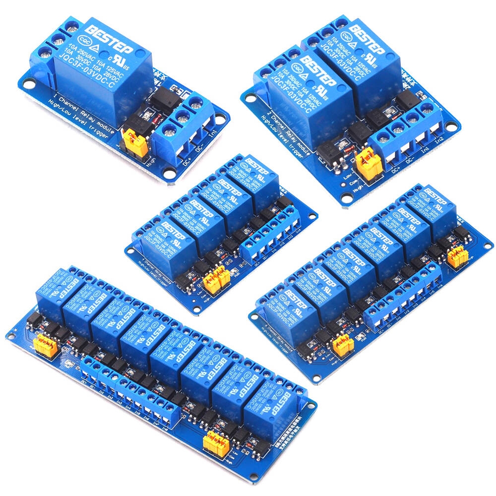
*-+5
It should be noted that the picture above shoes several different 'Relay Modules'.
The modules pictured contain 1, 2, 4, 6, & 8 relays, reflecting the fact that some systems
may require many relays. It should also be noted that different manufacturers use different coloured plastic for their relay module enclosures (many are not blue!).
Mouseover to Zoom
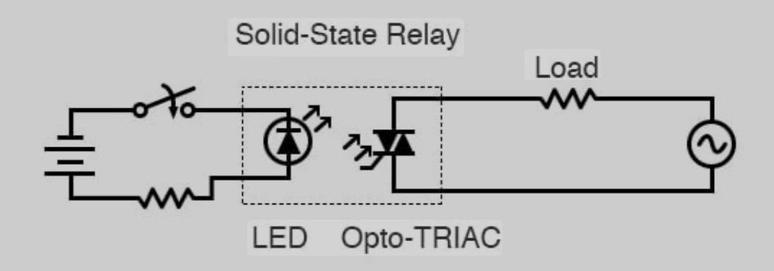
3.2 Solid-State Relays (SSR)
These have no moving parts. Instead of an electromagnet, they use semiconductors-typically triacs, thyristors,
MOSFETs, or transistors-to perform switching.
@Operation:%
A low-voltage control signal drives an internal optocoupler or transistor that triggers the main switching element,
isolating the control and load circuits optically rather than mechanically.
Advantages:
* Silent, fast, and wear-free operation.
* Extremely high switching life (millions of cycles).
* Resistant to vibration and mechanical shock.
Disadvantages:
* Slight leakage current when "off."
* Can only handle specific voltage and current ranges.
* More expensive than EMRs.
* Generate heat due to voltage drop across semiconductors.
Applications:
Industrial automation, lighting control, heating systems, and where high-speed, reliable switching is needed (e.g.,
process control and instrumentation).
Mouseover to Zoom
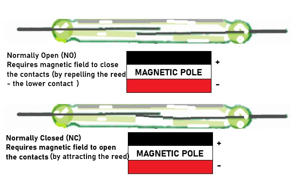
3.3 Reed Relays
*
A reed relay uses a reed switch-two ferromagnetic blades sealed in a glass capsule. The coil surrounding the capsule
creates a magnetic field that causes the reeds to attract and close the circuit.
Advantages:
* Very fast operation (microseconds).
* Compact and sealed from contaminants.
* Low contact resistance.
Disadvantages:
* Limited current and voltage handling capacity.
* Fragile compared to EMRs.
Applications:-
Telecommunications, test equipment, measurement systems, and signal switching.
Reed Relays (or reed switches) are also commonly used to monitor if doors and windows
are open/closed, and also by model railway enthusiasts to detect the presence of a
piece of rolling stock at a particular location, thus triggering the energising (or
isolation) of another piece of track, or a signal, crossing barrier etc.)
Mouseover to Zoom
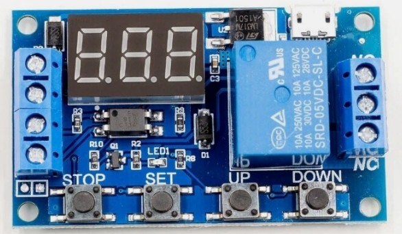
3.4 Time-Delay Relays
These include built-in timing circuitry that delays activation or deactivation after receiving the control signal.
They can provide on-delay, off-delay, or interval functions.
Applications:
Sequential control in industrial processes, motor start sequencing, and delayed switching in lighting systems.

Mouseover to Zoom
3.5 Thermal and Overload Relays
Used primarily for motor protection, these rely on bimetallic strips or thermistors that bend or change resistance
with temperature rise. When overheating is detected, the relay interrupts the circuit.
Applications:
Motor protection, heating equipment, and current overload detection.
Mouseover to Zoom
3.6 Latching Relays
A latching relay maintains its last state (on or off) after the control signal is removed. It uses a magnetic latch
or dual coils to “remember” its position.
Advantages:
* Consumes power only during switching.
* Useful in memory and energy-saving applications.
Applications:
Battery-powered systems, alarms, and remote control switching.
Mouseover to Zoom
3.7 Hybrid Relays
These combine the benefits of electromagnetic and solid-state designs-using solid-state devices for the initial
switching (to eliminate arcing) and mechanical contacts for carrying continuous current.
Applications:
Industrial power control, motor drives, and safety-critical systems.
4. Differences Between Relay Types
| Feature |
Electromagnetic |
Solid-State |
Reed |
Latching |
Time-Delay |
Hybrid |
| Switching Mechanism |
Mechanical |
Electronic |
Magnetic reed |
Magnetic/mechanical |
Time-Delay |
Hybrid |
| Response Time |
Slow (5–20 ms) |
Very fast (µs–ms) |
Very fast (µs) |
Similar to EMR |
Variable |
Fast |
| Lifespan |
Limited (10⁵–10⁷ ops) |
Long (10⁹ ops) |
Long |
Long |
Depends on type |
Long |
| Isolation |
Electrical |
Optical |
Electrical |
Electrical |
Electrical |
Both |
| Noise |
Audible |
Silent |
Silent |
Audible |
Depends |
Low |
| Current Range |
Up to 100 A |
Up to ~75 A |
Up to 2 A |
Varies |
Varies |
Up to 100 A |
| Cost |
Low |
Medium–High |
Medium |
Medium |
High |
High |
---
5. Power Handling Ranges
Relays are rated according to both coil voltage and contact load capacity.
* Coil voltage: Typically ranges from 3 V (logic-level control) to 230 V AC.
* Contact current: From milliamps (signal relays) to hundreds of amps (power relays).
* Switching voltage: From below 5 V DC (for logic signals) up to several kilovolts (in high-voltage types).
Examples:
* Miniature relays: 1-5 A at 12-48 V DC or 120-250 V AC.
* Industrial contactors: 10-100 A or more, often at 480-600 V AC.
* Solid-state relays: typically rated for 2-75 A continuous load, with voltage ratings from 24 V DC up to 660 V
AC.
Proper selection depends on load type (resistive, inductive, or capacitive) and environmental factors like
temperature, vibration, and duty cycle.
---
6. Integration into Systems
6.1 Control Interface
In a typical setup:
* A low-power control circuit (microcontroller, PLC, or sensor output) drives the relay coil or input pin.
* The relay output contacts switch the high-power circuit or load.
For microcontroller systems such as the Raspberry Pi Pico, the relay is usually driven through a transistor or
MOSFET, because the GPIO pins cannot supply enough current for the relay coil. A flyback diode is added across the
coil to protect against voltage spikes.
6.2 Mounting and Packaging
Relays come in several form factors:-
* PCB-mounted relays for small circuits.
* DIN-rail or panel-mount relays for industrial systems.
* Plug-in relays for easy replacement in control cabinets.
6.3 Isolation and Safety
To ensure electrical isolation:
* Optocouplers or isolation transformers are often used between control electronics and the relay coil circuit.
* Creepage and clearance distances on PCBs prevent arcing between low- and high-voltage tracks.
6.4 Integration Examples
* Automotive: Engine control, headlights, fans, and alarms.
* Industrial control panels: Motor starters, pumps, valves.
* Home automation: Smart lighting and appliance switching.
* Instrumentation: Signal routing in test equipment.
---
7. Relay Failures and Their Causes
Relays, like all components, can fail from mechanical wear, electrical stress, or environmental damage. Common
causes include:-
1. Contact Wear or Pitting:
Repeated arcing when switching high currents erodes the contact surface, increasing resistance and causing
unreliable operation.
2. Contact Welding:
Excessive current or inrush may fuse contacts together, causing the relay to remain permanently closed.
3. Coil Burnout:
Overvoltage or continuous overheating damages the coil insulation.
4. Spring Fatigue or Mechanical Jamming:
Physical degradation due to vibration, corrosion, or contamination.
5. Semiconductor Failure (in SSRs):
Overheating, transient voltages, or incorrect heat sinking can destroy internal devices.
6. Environmental Factors:
Dust, humidity, or corrosive gases can oxidize contacts or degrade insulation.
7. Improper Drive Signal:
Inadequate current or voltage at the coil may prevent full contact engagement, leading to chattering and accelerated
wear.
IF YOU SEE ANY OF THE ABOVE FAILURE INDICATIONS, DO NOT USE THE SYSTEM THE RELAY IS PART OF
BEFORE THE RELAY IS REPLACED
8. Mitigation and Protection Strategies
To ensure reliability, designers employ several techniques:
8.1 Electrical Protection
* Flyback Diodes (DC): Clamp reverse voltage spikes when the coil is de-energized.
* Snubber Circuits (AC): RC networks that absorb switching transients.
* MOVs (Metal-Oxide Varistors): Protect against voltage surges.
* Fuses and Circuit Breakers: Prevent overload and contact welding.
8.2 Contact Protection
* Use arc suppression circuits (RC or diode networks) across inductive loads to reduce arcing.
* Pre-charge resistors can limit inrush current.
* Select contact materials appropriate to load type (silver alloy for resistive, tungsten for inductive).
8.3 Thermal Management
* Ensure proper ventilation or heat sinking (especially for SSRs).
* Avoid continuous operation near rated limits.
* Use derating curves from datasheets for safe operating margins.
8.4 Mechanical and Environmental Protection
* Enclose relays to prevent dust and moisture ingress.
* Use sealed or hermetically packaged types in harsh environments.
* Minimize vibration through proper mounting.
8.5 Redundancy and Monitoring
* Critical systems often include dual redundant relays or feedback monitoring to detect contact failure.
* Microcontrollers can verify relay state using feedback circuits (e.g., sense resistor or auxiliary contact).
---
9. Detecting and Handling Relay Failures
Symptoms of Failure:
* Load does not turn on/off.
* Audible chattering or intermittent switching.
* Overheating or discoloration.
* Welded contacts causing continuous load operation.
* Circuit protection devices (fuses, breakers) repeatedly trip.
Diagnosis:
* Measure coil resistance to check for open or short circuits.
* Verify voltage at coil terminals.
* Check continuity across contacts when energized/de-energized.
* Inspect for visible damage or corrosion.
Response and Prevention:
* Replace failed relays with identical or higher-rated components.
* Implement predictive maintenance using switching cycle counters or thermal monitoring.
* Periodic inspection in industrial systems to prevent catastrophic downtime.
10. Effects of Relay Failure
The consequences of a failed relay depend on where it’s used and how it fails:-
* Contacts stuck open: Load fails to operate - possible loss of function, but usually safe.
* Contacts stuck closed: Load remains powered - potential overheating, fire risk, or equipment damage.
* Intermittent operation: May cause erratic system behavior, miscommunication, or data errors.
* Coil failure: Relay becomes unresponsive - control signal has no effect.
* SSR shorted output: Permanent conduction, leading to continuous power delivery and possible overload.
In safety-critical applications (e.g., medical devices, automotive braking, or industrial shutdown
circuits), relay failure can have serious consequences, hence redundancy and monitoring are essential.
11. Modern Developments and Trends
Recent advances in materials and semiconductor design have improved relay performance:
* Magnetic latching SSRs reduce idle power consumption.
* High-voltage MOSFET arrays allow precise, silent control for sensitive loads.
* IoT-connected relays with built-in diagnostics can report switching cycles, temperature, and contact wear in
real time.
* Microelectromechanical (MEMS) relays combine the isolation of mechanical relays with the size and speed of
solid-state technology.
These innovations extend relay use into new fields such as smart energy systems, renewable energy control,
and autonomous vehicles.
12. Summary
An electronic relay is a versatile, essential component bridging the gap between control electronics and power
systems.
Its operation-whether mechanical or solid-state-provides safe electrical isolation, amplification of control
signals, and reliable automation.
* Types: Electromagnetic, solid-state, reed, latching, time-delay, hybrid, and others.
* Applications: Power control, automation, communications, instrumentation, motor drives, and safety systems.
* Power Handling: From microamps in signal circuits to hundreds of amps in power systems.
* Integration: Easily interfaced with logic circuits and industrial controllers through drivers, isolators, and
protective networks.
* Failure Mitigation: Through suppression, redundancy, environmental sealing, and predictive maintenance.
* Failure Effects: Range from simple non-operation to dangerous continuous energization - manageable through
good design and monitoring.
In summary, whether switching a lamp, protecting a motor, or managing industrial automation, electronic
relays remain one of the most practical and indispensable devices in electrical and electronic engineering. Their
blend of simplicity, reliability, and adaptability ensures that relays will continue to serve as vital control
elements across both traditional and modern technologies.
© 2025 Professor Petabyte